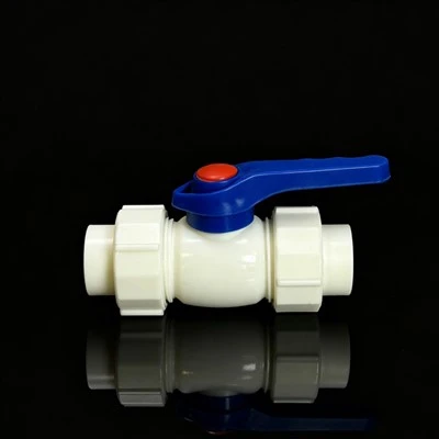
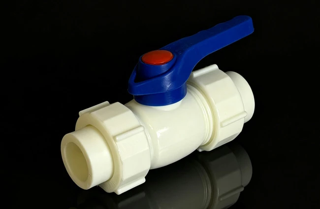
With its no-pipe-cutting replacement advantage, the PPR double union ball valve has become a standard on-off component in residential and engineering water systems. Yet non-standard installation and inadequate pressure testing often lead to joint leakage, valve core damage, and switch failure, shortening valve service life. Only by following standard procedures and acceptance requirements can the convenience and sealing reliability of the double union structure be fully realized.

I. Pre-Installation Preparation and Inspection
1. Specification and Visual Inspection
Verify that the nominal diameter and pressure rating match the piping; check that the valve body and union nuts are free of cracks and deformation, the handle operates without sticking, and the sealing components are fully seated and flush in their grooves.
2. Piping and Tool Preparation
Clean out sand, grit, and debris inside the pipe to prevent impurities from entering the valve body and scoring the sealing face of the valve core. Prepare a fusion tool, pipe cutter, and adjustable wrench of the corresponding specifications, and calibrate the fusion tool to the standard range of 260°C ± 10°C.
3. Installation Position Confirmation
Give priority to a location that is easy to access and convenient for later maintenance, with the handle installed horizontally by default. Avoid areas prone to standing water, direct sunlight, and heavy impacts, and leave adequate clearance for nut assembly and disassembly.
II. Standard Installation Procedure
1. Fusion Socket Pre-Connection
Slide the union nuts and PPR socket onto the pipe in sequence, complete the fusion between the socket and pipe according to standard procedure, ensure the insertion depth is not less than the minimum socket depth specified for the corresponding pipe diameter, and allow to cool undisturbed until fully set. Do not forcibly twist the pipe during cooling.
2. Valve Body Assembly
Clean the sealing faces at both ends of the valve body and confirm the sealing rings are seated without displacement. Align the valve body with the sockets on both sides and tighten the union nuts at both ends evenly and alternately to avoid uneven stress that could crack the body.
3. Switch Function Pre-Test
Operate the handle 3 to 5 times after assembly, cycling the valve core between the fully open and fully closed positions without testing the half-open state, to confirm smooth operation and a clear 90° stop with no sticking or looseness. After testing, leave the valve core in the fully open position before proceeding to system pressure testing.
III. Water Pressure Test and Acceptance Specification
1. Individual Valve Pressure Test
The individual valve has already passed its shell strength test at the factory in accordance with GB/T 13927, with the valve core in a partially open position and the test pressure set at 1.1 times the rated pressure.
2. System Piping Pressure Test Standard
For cold water piping, the test pressure is 1.5 times the working pressure and not less than 0.6 MPa; for hot water piping, it is 1.5 times the working pressure and not less than 1.0 MPa. The test pressure must not exceed 1.5 times the valve's rated pressure, and forced pressurization with the valve closed is strictly prohibited.
3. Valve Core Position Requirement
During system pressure testing, the valve core of the PPR double union ball valve should be placed in the fully open position to ensure continuous water flow through the piping and prevent localized pressure buildup that could damage the sealing components.
4. Pressure Stabilization and Acceptance Criteria
After pressure is raised to the specified level, stabilize it for 30 minutes with a pressure drop not exceeding 0.05 MPa. At the same time, check that the union joints, valve stem area, and valve body surface show no leakage or deformation. Passing both criteria constitutes a qualified test.
5. Post-Test Treatment
After a qualified test, slowly release any residual pressure from the piping and flush it with water; flush once more after testing to confirm no debris remains. For concealed work, retain pressure test records and photographic documentation, and only proceed with subsequent construction such as slot sealing or ceiling installation after confirming everything is in order.
IV. Common Installation Problems and Prevention
1. Union Joint Leakage
Usually caused by uneven tightening force on the nuts or displacement of the sealing components. Prevention: tighten the nuts evenly and alternately, check that the sealing rings are flush in their seats before installation, and do not use deformed or aged sealing components.
2. Incomplete Fusion of the Socket Joint
Usually caused by insufficient heating time or temperatures that are too low. Prevention: strictly control fusion temperature and duration; when working below 5°C, adjust according to the material manufacturer's process card and raise the fusion tool setting when necessary.
3. Valve Body Cracking
Usually caused by excessive one-sided force or forcibly correcting the pipe angle. Prevention: never use a cheater bar to overtighten the nuts; if the piping is misaligned, adjust the pipe position first and do not force the valve body into alignment.
4. Valve Core Clogging from Debris
Usually caused by failure to clean the piping or flush it after testing. Prevention: flush the inside of the piping with water before installation, and after pressure testing open the valve fully to flush the piping once more before it is officially put into service.